Frontpage
-
Transition to deployment phase approaching: update on project status
Impressive progress has been made across the entire collaboration, with production progress vital as we continue to progress towards deployment in the LHC tunnel. The upcoming Collaboration Meeting will be an exciting time to meet just after the start of deinstallation of the machine, to reflect on what we have achieved so far and what…
-
Collaboration status in advance of Long Shutdown 3
As Long Shutdown 3 approaches, delivery schedules from the collaborations are more important than ever. A collaborative effort has seen good progress across the project worldwide, including from more-recent agreements with Pakistan and Brazil. International collaborations remain a central pillar of the High-Luminosity LHC (HiLumi LHC) project. Production activities are progressing well across all existing…
-
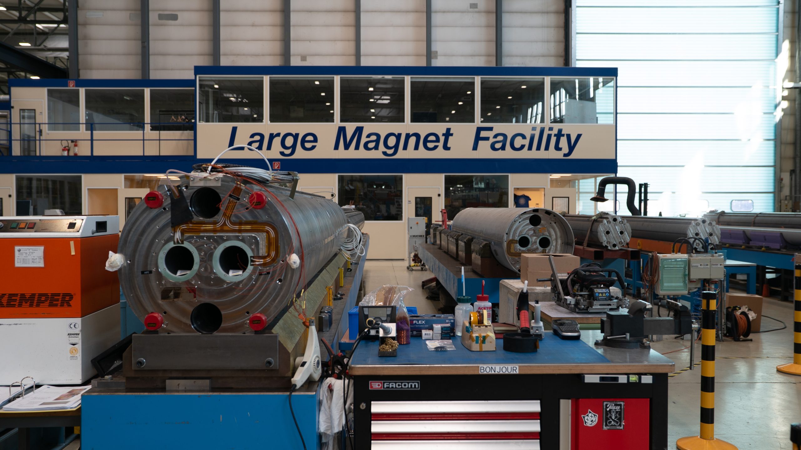
HiLumi LHC magnet programme transitioning from fabrication to integration
The High-Luminosity (HiLumi) LHC magnet programme continues to advance steadily across all collaborations, with major milestones reached in production, testing, and system integration. A significant highlight of the past 6 months is the cooldown of the Inner Triplet (IT) String, now at 1.9 K, with the first magnets already powered, marking an important step towards…